The store will not work correctly in the case when cookies are disabled.

Litter-Robot 3: Wiring Harness Installation Guide
Preparation
Wire Harness Kit includes:
- Power jack with connectors
- Backup battery connectors
- Motor wires
- Hall effect sensors
- Cat sensor wires
- Bonnet connector wires
Tools Needed:
- 8-inch #2 Phillips Screwdriver
- Needle-nose pliers
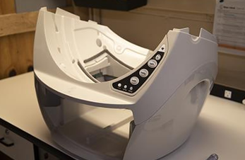
- Press the Power button to turn the unit off, and unplug it from the wall.
- Remove the bonnet by pressing the latches on both sides of the bonnet then lift while rotating it backwards. There are two plastic tabs on the back of the bonnet that should slide up and out of the base. Set the bonnet aside.
- Remove the globe and set aside.
Remove the waste drawer and set aside.
![]()
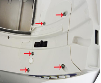
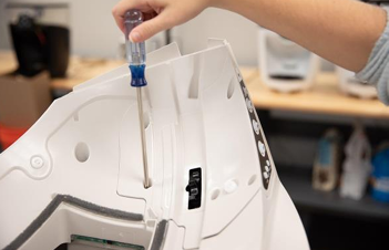
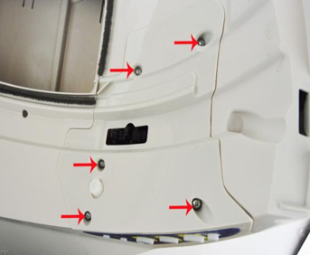
- The plastic component that covers the control panel on the base is called the control panel cover. Unscrew the 5 screws to remove the cover.
![]()
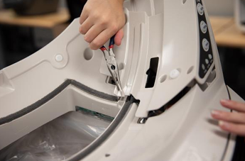
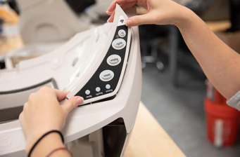
- Separate the control panel cover from the control panel by pushing the buttons through and lifting up. Set the control panel cover and screws aside.
Note: The circuit board and keypad may be held in place by a piece of tape (assembly aid). If present, simply remove it; it is not required for reassembly
![]()
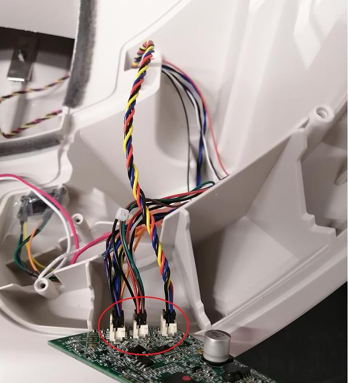
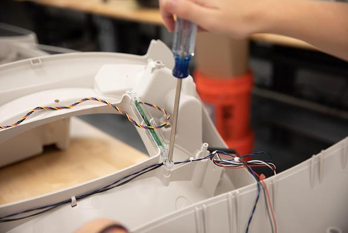
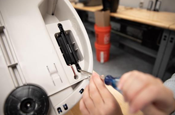
- Turn the keypad and circuit board over and unplug the three connectors: 4-pin (DFI drawer full indicator), 6-pin (motor and power), and 8-pin (hall effect sensor). Set the circuit board aside.
![]()
Remove the old wire harness
- Unplug the motor wires. Follow the red and white wires, which connect to the back of the motor to where they are attached to the brown and green circuit board wires, and disconnect them by pulling apart the quick disconnects. Remove the motor and set it aside.
![]()
Note: These can be difficult to pull apart; using the needle nose pliers may help you to get a better grip.
- To the left of the motor there is a small plastic bracket with two sensors mounted on it. These are called the hall effect sensors. Remove hall effect sensor and bracket and set aside. Save the tape as it will be necessary for reassembly.
![]()
- Where the wires descend into the base there is a small, black, L-shaped piece, called the bulkhead plug. Remove the bulkhead plug and set it aside.
- Reach in through the opening for the waste drawer and pull the disconnected wires into the base.
Note: These can be tricky to pull through. Try pulling the 4-pin DFI connector through first, followed by the 6-pin (motor and power), and finally the 8-pin (hall effect sensor).
- Flip the base upside down.
- If the unit has a backup battery:
- Remove the backup battery.
- Remove the two screws holding the backup battery bracket in place.
- Set the bracket to the side.
- Unplug the red and black wires from the battery at the quick disconnects.
- Set the battery aside.
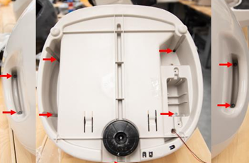
- Remove the 9 screws from the bottom of the base.
![]()
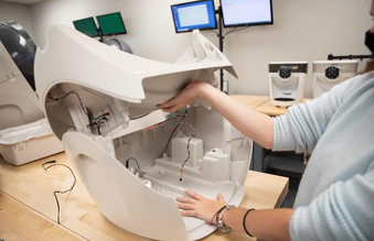
- Flip the base back upright and gently remove the top part of the base. Pull up on the front of the top half of the base and flip it towards the back of the unit, keeping in mind that wires will still be attached.
![]()
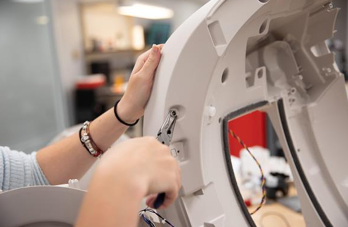
- The clear brackets on either side of the opening in the top of the base are the DFI harnesses. Remove one screw from each of the DFI harnesses, on the side nearest where the purple and black wires are routed.
![]()
Note: Do NOT remove the entire DFI Harness.
- Locate where the purple and black wires plug into the metal bonnet sensing tabs. Unplug these wires and remove them from under the DFI harnesses and any tabs holding them in place.
![]()
- Pull the red and black backup battery wires up through the bottom of the base.
![]()
Note: Pulling these wires out one at a time may make this easier.
- The port where the power cord plugs into the back of the unit is called the power jack. Unscrew the nut which is attached to the outer side of the power jack. Remove the nut and washer and set them aside. Push the power jack through its mounting hole into the base. Put the nut and washer back onto the detached power jack.
![]()
Note: The needle-nose pliers may make it easier to hold the nut while you unscrew it.
- The silver plate in the back-center of the base is called the cat sensor. Unplug the cat sensor at the back block where it connects to the blue and black wires. Be careful not to bend the force sensor. The wires will be tucked under routing tabs along the back of the unit. Make sure to remove the wires from under these tabs.
![]()
- Everything should now be disconnected. Remove the old wire harness from the unit.
Install the new harness
- Remove the wire harness from its packaging. Locate the black sleeve that covers the hall effect sensors. Make sure that this sleeve stays over the sensors until they are ready to be connected.
- Remove the nut and washer from the new power jack and set them aside. Insert the power jack into the mounting hole at the back of the base. Place the washer and then the nut back onto the end of the power jack which is now coming out of the base, and tighten the nut so that the power jack doesn’t wiggle.
![]()
Note: The needle-nose pliers may help to grab the nut while you tighten it down.
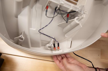
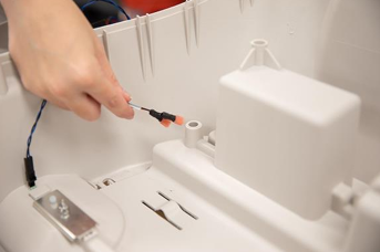
- Plug in the cat sensor. Using the black L-shaped connector at the end of the black and blue wires, plug in the cat sensor, with the thickest portion of the connector pointing towards the front of the waste drawer cavity. Tuck the blue and black wires under the three tabs along the back side of the base.
![]()
- Push the red and black backup battery wires through the hole at the bottom of the base. Note: This may be easier if you push the wires through one at a time.
![]()
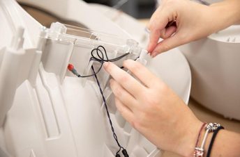
- Plug in the bonnet sensor. Locate the metal tabs along the side of the upper base. Take the purple and black wires and attach them to these tabs. The purple wire should plug in closer to the side where the wires are routed. Make sure that the metal tabs are flat against the top face of the base once you have them plugged in. Note: These tabs are flexible, and holding them down from the top side of the base will prevent them from bending or moving when you plug the wires in.
![]()
- Route the purple and black wires from the harness along the same path as the black wires which are already connected to the DFI. Reattach the screws which were removed from the DFI Harnesses.
![]()
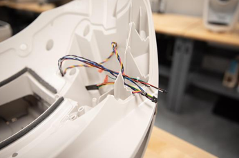
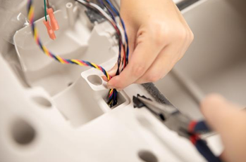
- Feed the connectors up through the top of the base. Start by feeding through the black sleeve which contains the hall effect sensors. Then feed through the 8-pin connector (hall effect sensors), followed by the 6-pin connector (motor and power), and finally the 4-pin connector (DFI).
![]()
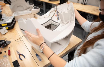
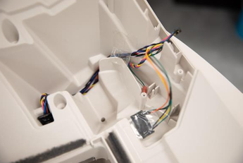
- Ensure that all wires are tucked to the back right of the waste drawer cavity. Flip the top of the base back onto the bottom of the base and make sure that it nests correctly.
![]()
- Flip the entire base upside down and replace the 9 screws into the bottom of the base.
![]()
- If the unit has a backup battery, plug the battery back in. Ensure that the wires route through the small channel near the battery and into the cavity with the battery resting on top of the wires. Replace the black bracket which holds the battery in place by reattaching the screws located at each end.
![]()
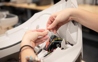
- Flip the base back upright and pull the wires gently to make sure they are taut. There should be plenty of slack for wire routing.
![]()
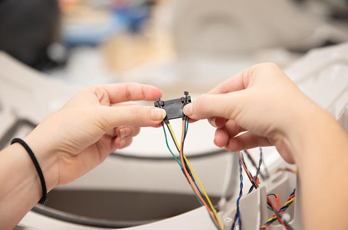
- Replace the hall effect sensors. Take the black bracket that mounts the hall effect sensors to the base, and insert the sensors into the two grooves on the bracket. This is done by putting the wires through the grooves in the bracket, and then GENTLY pulling the hall effect sensors back so that they nest into the bracket. Facing the bracket with the mounting grooves at the top edge, the wires should be oriented so that the yellow and orange wires are the middle two wires, with the yellow wire on the left and the orange wire on the right.
![]()
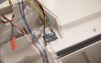
- While holding the hall effect sensors in place, insert the pegs on the bottom of the bracket into the two holes in the top of the base. When done correctly, the hall effect sensors should be directly next to the two ribs that lead out from the mounting holes. Using the tape that was removed when the old sensors were removed, tape the sensor bracket down, making sure that the tape stays within the indentation for the control panel cover.
![]()
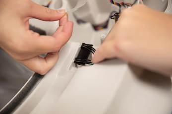
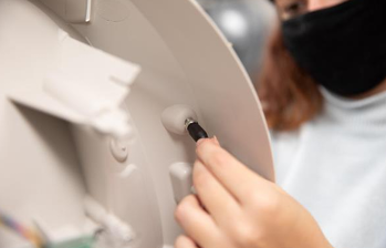
- Locate the hole that leads from the inside of the base which the wires are routed through. Hold the wires against the edge of this hole, and reinstall the bulkhead plug.
![]()
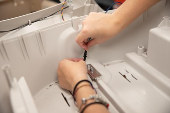
- Route the wires through the channel which runs through the motor cavity. Then orient the motor so that the gear is toward the front face of the unit. Tuck the red and white wires underneath the motor, and place it into the cavity so it holds the wires in place. Make sure that no wires interfere with the gear on the motor.
![]()
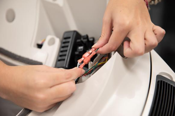
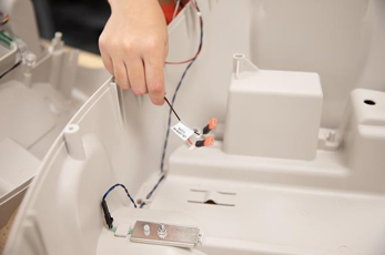
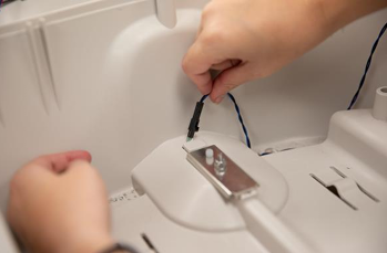
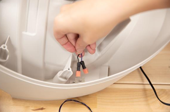
- Plug the red and white wires from the back of the motor into the brown and green wires from the wire harness. The red wire should be connected to the green wire, and the white wire should be connected to the brown wire.
![]()
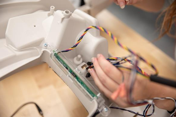
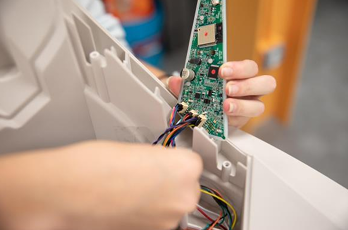
- Reattach the three wire connectors to the circuit board. The 4-pin connector goes on the 4-pin header, the 6-pin connector goes on the 6-pin header, and the 8-pin connector goes on the 8-pin header.
- With the headers facing you, you will not use the header on the far right of the circuit board. Each connector is keyed with a top and a bottom so that it will only fit in one way. If you feel any resistance, flip the connector over and try to attach it again.
![]()
Make sure the wires attached to the circuit board are tucked behind it in the wire channel.

Reassemble
- Reassemble the control panel cover onto the circuit board and keypad by pushing the keypad buttons back through the cover. Make sure to keep the silicone keypad wrapped around the edges of the circuit board.
![]()
- Look through the opening where the black gear protrudes and make sure no wires are visible. If wires are visible, remove the control panel cover, tuck them into the wire channel, and secure them with the piece of tape. Once in position, the edges of the control panel cover should rest flush with the base.
![]()
- Attach the control panel cover by tightening the 5 screws. Do not over-tighten.
![]()
- Reinstall the waste drawer.
- Replace the globe, making sure it is on straight and in its tracks. At the back of the globe, turn the black key into the key pocket.
- Replace the bonnet by inserting the bonnet tabs into the rear bonnet slots then press the latches while rotating it forward, until the latches click into place.
- Plug the Litter-Robot into the wall.
- Press the power button to turn the unit on.
Once the initial clean cycle is complete, the unit should return home displaying a blue 'ready light' status.
![]()

Need technical support?
Our easy-to-use troubleshooting wizard can help you solve your issue quickly and will submit a support ticket in the event your issue is not solved.
Didn't find what you're looking for?
Phone and Chat support available Mon-Fri: 9AM-7PM EST and Sat: 9AM-5PM EST, or submit a ticket anytime.